DCVG Ltd are pleased to announce the introduction of new pipeline survey equipment, the Quantum Plus CIPS Data Logger. This state of the art equipment has been specifically designed so that CIPS data, for the first time, can be properly collected simultaneously as a true DCVG Coating Fault survey is carried out. This allows two independent techniques, CIPS and true DCVG (using an analogue meter) to be cost effectively run simultaneously thus satisfying a major requirement in data collection as set out in ECDA Specifications. The Quantum Plus equipment uses GPS technology to stay synchronised with newly developed GPS controlled multiple interrupters used to pulse the pipeline CP.

A display screen, which is a UNIQUE feature of the Quantum Plus Data Logger, displays the interruption cycle allowing the survey pulse and data which is logged, to be viewed. Both the Anodic and Cathodic “spikes” can be avoided by locating the voltage sampling indicators (T shaped) to the correct positions of the ON and OFF cycle. The Quantum Plus logger has two alternative synchronisation methods for determining the correct position on the pulse at which to record potentials to exclude spike errors and to cover as many different surveying conditions as possible.

One method (the default method) utilise GPS technology. A small satellite receiver aerial (the size of a PC mouse mounted on the surveyors cap) picks up the NAVSTAR one second pulse, and interprets the string of data attached to the pulse to recognise the particular second and then will synchronise with all interrupters and other loggers that use same technique to check synchronisation at 0, 5,10,15, etc seconds of a minute. The aerial also picks up the coordinates, date, time of day etc and these are logged every 5 seconds for use to work out distance, and effects of interference with a similar stationary logger. The other method for use in locations where the satellite signal is poor because of shielding, such as in forests or cities involves the Quantum Plus logger recognising the moment at which the current is switched ON or OFF. This enables the time when CIPS Potentials are automatically recorded to be set, and the accuracy of the measurements maintained after prior being set to synchronisation at a location where the satellites can be seen. The status of the satellite signal is always visible on the Quantum Screen.

The Quantum logger has a built in library of seven pipeline Right of Way Features. The eighth feature alows the entry of specific data using the alpha numeric keyboard. Hot Key facilities enable data entry times at Features and Faults to be reduced to a minimum leaving more time for the actual survey.
The Quantum Plus logger comes with its own DCVG Ltd designed data download program to sort, calculate and prepare data for the CIPS software graph presentation package. This seamless integration leads to minimal data processing time and hence faster report preparation. Data is also suitable for entry into more sophisticated data analysis software such as DCVG’s ECDA data presentation and analysis programs.

The CIPS Quantum Plus Equipment uses many components in common with DCVG’s Analogue DC Voltage Gradient Equipment. This compatability reduces the number and hence cost of spares that must be carried during surveys and ensures their ready availability in case of replacement.
Careful design incorporating many inovative features has been given to surveyor convenience in operating the equipment. For example, the large size wire spools used for the “disposable” Trailing Cable means that spool changes are only required approximately every 5 Km a real bonus in difficult surveying conditions. The one metre long low maintenance reference electrodes, are strong and can be used to aid traversing difficult terraine. A detailed method statement is also available that identifies step by step the procedure for operating a CIPS survey, taking the data in the correct manner to determine the location and to quantify the effectiveness of cathodic protection along a pipeline route. Similar Method Statements are available for running the two techniques, CIPS and DCVG at the same time or running the two techniques in cooperation with a metal loss in line inspection pig run.
Dettaiilled Quanttum Pllus CIIPS Equiipmentt Capabiilliitty Speciiffiicattiion
Quantum Plus Data Logger maximum Voltage Range plus/minus 25 Volts.
Voltage Range variable, plus or minus 25V, 10V, 5V, 2.5V, 1V, 500mV, 250mV, 100mV, 50mV, 25mV, and 10mV.
Quantum Plus Data Logger synchronised using the one second Satellite Pulse and alternatively on the front edge of the pulse.
The Quantum Plus CIPS Data Logger is synchronised with the CP Interrupters, both being controlled by NAVSTAR multi-satellite time pulses.
The Interrupter ON/OFF sequence is variable from 0.45 seconds ON, 0.8 seconds OFF for combined CIPS surveys with DCVG to 3 seconds ON two seconds OFF for pure CIPS. This pulsing frequency variability allows CIPS and DCVG surveys to be carried out simultaneously or independently. (The ON and OFF times add up to a number which can be divided uniformly into 5 seconds, the sychronisation time interval.)
The actual ON/OFF pulse is viewed on the Quantum Plus Data Logger LED Screen at actual time of taking potential measurements.
The time of measurement after switching OFF and ON the CP can be varied to exclude Anodic or Cathodic spike errors.
A T shaped indicator indicates the time location of the measurement on the pulse on the screen.
The width of the pulse can be indicated as a check on Interrupter Synchronisation.
In the CIPS mode the ON and OFF readings for every pulse of the CP system is recorded automatically. The reading is an average reading taken of many observations over a 150 millisecond interval from the T marker location.
The Quantum Plus Data Logger Memory at 32 Megabyte will hold more than 62.500 lines data. The normal Microsoft Excel program used to download can only accommodate 65,000 lines of data.
The Number of Data Points Logged in the Quantum memory is given on the CIPS Screen.
The actual values for ON and OFF potentials being recorded are given on the screen.
The status of the GPS and type of synchronisation being used is indicated on the screen.
A series of hot keys allow CIPS, Features, Pulse width, GPS or other Distance Measurement facilities to be rapidly selected.
Epicentre CIPS measurements at DCVG indications can be independently logged from conventional CIPS data.
When connected to a GPS aerial the date and time of day plus GPS Location of all measurements is recorded every 5 seconds. This allows Surveyor performance to be monitored.
The drift in Interrupter synchronisation is less than 1 millisecond in 5 minutes. The Interrupters and Quantum check and adjust synchronisation every 5 seconds. Drift of synchronisation with Quantum and its Interrupters is not an issue as it is accurately monitored and rechecked.
Common components are used where possible between the Quantum Plus CIPS equipment and our analogue DCVG meter. This results in fewer spares and hence costs, etc when operating the equipment under survey conditions.
Common Pipeline Right of Way Features (Test Posts, Fences etc) built into the Quantum Data Logger Memory can be independently logged during a survey. The 8th feature option allows entry using the alphanumeric keyboard.
The Quantum Plus Data Logger and Interrupters are charged with 19V AC from a 110/220 Volt AC step down charging unit. Each piece of equipment has their own built in rectifiers operating from common charger units.
The Quantum Plus Data Logger will operate for several days between charges. The Interrupters will operate for 36 hours between charges. An additional battery pack is available to extend the operational life of Interrupters. Alternatively the battery charger operated from the mains electricity at a rectifier may be used to maintain Interrupter operation continuously.
The download Baud Rate for transferring data from the Quantum Plus Data Logger to a PC is 57,600.
The Quantum Plus CIPS Download program, sorts and allows data editing prior to its entry into the CIPS Graph program.
Download Data is also in a form where it can be directly entered into sophisticated data analysis programs such as ECDA.
Quanttum Pllus CIIPS Equiipmentt Speciiffiicattiion
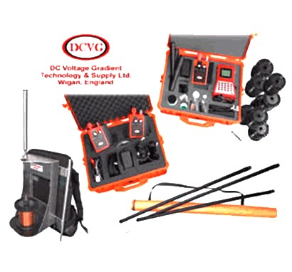
The following items are the typical component parts that make up one full set of Quantum Plus CIPS / DCVG Equipment.
1 Satellite Synchronised CIPS / DCVG Quantum Data Logger.
3 Copper/Copper Sulphate Reference Probe Electrodes.
3 Reference Probe Handles.
4 Satellite Aerials for Quantum Data Logger and 3 sat.synch.Interrupters.
3 Satellite Synchronised Interrupters Variation 3 for CIPS and DCVG Surveys with variable Pulse Frequency.
Quantum Data Logger Download CD.
Computer and GPS Connection Leads.
Probe Electrode and Wire Dispenser Connection Leads.
Accessories: - Battery Chargers, Special Electrode Tips and Holders, PTFE Tape, Washers, Squeezy Bottle, Copper Sulphate Crystals.
User Manual.
Weatherproof / Indestructible Carry Cases for Equipment and probes.
6 x 12.5cm wire reel blanks.
Reel winding spindle.
Complete Wire Dispenser / Quantum Battery Backpack A full range of Spares are also available ex-stock. A Basic set having fewer parts is also available.


 Global Service Hotline: