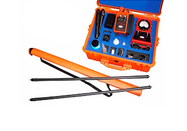
John Mulvany & Dr.John Leeds Experimenting During The Initial Development And Testing Of The DC Voltage Gradient Technique In The Australian Desert In The Early 1980’s
The DCVG technique is one of the two most important inspection tools used in the ECDA concept to inspect buried pipelines. The other is CIPS. Both DCVG and CIPS utilise the pipelines CP system, one of the two corrosion mitigation techniques applied to the outside of pipelines. The NACE SP 0502–2008 which is a virtual reissue if the original 02 document perpetuates gross errors in the way DCVG is classed the same as ACVG. It is NOT the same. See Page 3 for a list of Coating Fault properties and Information Sheet 7 for limitations of AC and EM techniques.
CIPS and DCVG are the only two inspection methods that assess the effectiveness of a pipeline Cathodic Protection system.

Second To None. Predominant (29 YEARS) Expertise In DCVG Technology – “We Lead Others Copy”
DCVG was first was discovered by John Mulvany an Australian ex Telecom Corrosion Engineer, who worked extensively with Dr.Leeds of DCVG Ltd. in developing the technique and its application. This gives DCVG Ltd. an unparalleled 29 years experience in DCVG Technology. This expertise backed by the excavation and inspection of several thousand DCVG fault indications, plus the interpretation of DCVG electrical data to what is found during excavation is passed onto users of our DCVG Equipment. Technology transfer is via detailed Training Courses and ongoing e mail Technical Support. Finding coating faults is not difficult but the correct interpretation of survey data to identify what coating faults to cost effectively repair requires experience and the type of expertise that is available from DCVG Ltd.
Principle of the DC Voltage Gradient Technique
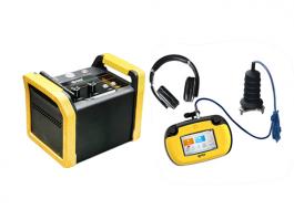
In Cathodic Protection when current flows through the resistive soil to the bare steel exposed at faults in the protective coating, a voltage gradient is generated in the soil. The larger the fault the greater the current flow and hence voltage gradient and this is utilised in the technique to prioritise faults for repair. The voltage gradient is observed by measuring the out of balance between two copper sulphate electrodes utilising a specially designed milli-voltmeter. When the two electrodes are placed 1.5 meters apart on the soil in the voltage gradient from a coating fault, one electrode adopts a more positive potential than the other which allows the direction of current flow to be established and fault to be located. To simplify the fault location interpretation, the applied CP is separated from all other DC influences such as Tellurics, DC Traction etc, by pulsing the local CP ON and OFF in an unsymmetrical fashion. The pulsing DC can be from the pipeline CP system itself, or from an independent source such as a portable DC generator or batteries utilising a temporary groundbed and impressed on top of a pipelines existing CP system.

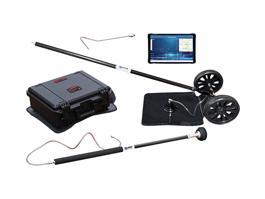
In surveying a pipeline, the operator walks the pipeline route testing for a pulsing voltage gradient at regular intervals. As a fault is approached, the surveyor will observe the milli-voltmeter needle begin to respond to the pulse, pointing in the direction of current flow that is towards the fault.
When the fault is passed the needle direction completely reverses and slowly decreases as the surveyor moves away from the fault. By retracing to the fault, a position of the electrodes can be found where the needle shows no deflection in either direction (a null). The fault is then sited midway between the two electrodes. This procedure is then repeated at right angles to the first set of observations, and where the two midway positions cross is the epicentre of the voltage gradient. This is usually directly above the coating fault.
In order to determine various characteristics about a fault, such as severity, shape, corrosion behaviour, etc, various electrical measurements around the epicentre and from epicentre to earth are made for interpretation.
The beauty of the DCVG technique is that it utilises the existing pipeline CP system at its normal setting wherever possible and hence results reflect the intimate interaction between the protective coating degradation and the effectiveness of CP at individual coating faults. This is very powerful information in the fight against corrosion. No AC or Electromagnetic Technique offers such a direct study capability.
The DCVG Technique can be applied in City Streets, Process Plant and Refineries, across Rivers and Estuaries, Swamps, Parallel Pipeline systems, to Gas, Oil, Chemical and Water Pipelines. Also DCVG can be used to evaluate the protective coating on Telephone and Power Cables.
The detailed information provided by DCVG Technology when analysed with other information such as Pipe to Soil Potential, Soil Resistivity and Composition, pH, Temperature, Operational History, Inline Inspection Tool Data, etc through a program such as DCVG Ltd’s ECDA program enables pipeline rehabilitation requirements for the Steel, Coating and CP to be prioritised for the most cost effective repair.

 Global Service Hotline: